Category Archives: 4-Extensions

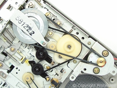
CE-152 : Inside and problem solving

This morning i received a mail from an australian friend, Bronte, telling me about belts problems in his CE-152.
Do you have problems with your Sharp CE-152 or want to look inside ?

Someone explains this tape recorder better than i can do : www.petervis.com
sharp-ce-152-motor-drive-belt-configuration

You can find the belts on eBay. But some vendors are very expensive… search… search…
For example : this one in China or this one in UK

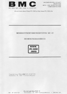
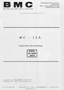
BMC : The MC-12 user manual and MC-12A supplement

Hello, we all have to thank AXEL for these documents !
I contacted him some days ago about his MC-12A picture on his website :
http://www.askrprojects.net/calcs/calcs.html

He searched everywhere in his hard-drives and found two scans of the manuals.
The pictures had black margins with text inside.
With my favorite image processing software (Aperture) i corrected it, sometimes with letters by letters words reconstructions.

Here are the manuals :

BMC_MC-12_User_manual
Download
BMC_MC-12A_Supplement
Download

Thanks you again Axel !

TRAMsoft Gmbh, Swiss know-how ! (part 4)

It’s time to let Reto Ambühlerr describe his company, products and story :

TRAMsoft GmbH – History and Facts

1. The Name

The name TRAMsoft derives from the initials of the founders Thomas Müller and Reto Ambühler. It is written in 4 uppercase and 4 lowercase letters to reflect the fact, that the SHARP PC-1500 supports uppercase and lowercase letters. The previous models supported only uppercase letters.

2. The Beginning

The company TRAMsoft Ambühler & Müller was founded in 1983 as a general partnership, but its history goes back to 1980, when Thomas and Reto discovered their passion for programmable pocket computers while they were students at the University for Applied Science, then known as “Technikum Winterthur”. They used their Texas TI-59 to solve many problems in math, physics, electro technics and many other disciplines during their study. Thomas once even wrote a program to find the measure of German poems.
In 1982 SHARP released the BASIC programmable pocket computer PC-1500. Thomas and Reto became fascinated by this machine from the very beginning. Even though SHARP did not unveil the details about the internal programming, the two started to explore the operating system step by step. After many sleepless nights, they disassembled the complete operating system by a kind of reverse-engineering the operating system’s ROM. It turned out, that the PC-1500 was design for flexibility and extensibility at a very high degree. Thomas and Reto developed not only an external hardware that allowed to add new BASIC commands, but they also wrote their own assembler to compose the required software.
They continued to develop additional hardware and software for various purposes, even for industrial applications.

3. The Products

3.1 Toolkit

The TRAMsoft Toolkit was the first commercial product sold by TRAMsoft. The hardware consisted basically of an 8 kB EPROM and a frequency modulation/demodulation unit. The former could be programmed to store up to 4 different sets of BASIC commands, the latter supported writing and reading programs to and from a cassette recorder.
TOOL1 provided a set of additional BASIC commands for easier and more efficient editing, such as FIND and RENUMBER plus commands for modular programming.
TOOL2 provided 25 times faster save and load operation than the built-in CSAVE and CLOAD commands plus additional options to support modular programming.
TOOL3 was a collection of additional functions such as decimal – hexadecimal conversion, extended error handling, operations to manipulate variables including REDIM, string manipulation and more.
TOOL4 provided extensive support for statistics and so called “synthetical programming”. The latter means that the BASIC program could modify itself during execution.

3.2 Expansion Box

With the TRAMsoft Toolkit and optional devices from SHARP, users were faced with the problem, that they could not use more than one external device at a time. To overcome this problem, TRAMsoft developed the so called expansion box or E-Box for short. The E-Box provided four connectors, so users could connect up to four external devices at the same time. Each port could either be configured by switches or by software. For maximum flexibility, read and write access to each port could be controlled individually. This allowed to even connect devices which covered the same address range.

3.3 A/D Converter

Thomas and Reto always had been fascinated by data acquisition and process control applications. Therefore they developed a data acquisition interface or A/D converter for short. The first device, which became known as “Standard A/D Converter”, supported 8 input channels for data acquisition and 4 digital output lines. It provided up to 6 conversions per second with 12 bit resolution.
When the PC-1600 came out, even more sophisticated applications became possible and faster data conversion was needed. TRAMsoft developed the “Advanced A/D Converter” which supported up to 1500 conversions per second. It also had 8 channels and 4 digital output lines, but the number of A/D channels could be doubled with an optional extension which also added 4 digital input and 10 digital output lines. In order to read and store data at such a high rate, the software had to be written in machine language. It stored the data into a DIM variable so it could be further processed with programs written in BASIC. An optional program written in machine language even provided asynchronous data acquisition, which means a program running in the background collected and stored data while a BASIC program run in the foreground, both completely independent of each other.

3.4 Parallel/Floppy Interface

With the increasing number of programs and their growing size, a need for nicer printing and more comfortable storing arose. Both issues were addressed with the parallel/floppy interface. The parallel interface could either be used for input/output operations or to connect a printer with a parallel interface, also known as Centronics interface. The built-in software provided commands such as LLIST to print out program listings and LPRINT to print output from a BASIC program.
The floppy interface on the other hand supported storing and loading programs and date to and from floppy discs. The interface supported the Commodore VC-1541 5¼” floppy drive.

3.5 Memory Modules

The PC-1500 and the PC-1500A were both equipped with a slot which could accommodate a memory module with up to 32 kB capacity. TRAMsoft first developed a 32 kB memory module which could either be equipped with a RAM or an EPROM chip. The former provided additional space for BASIC programs, DIM variables and/or software written in machine language, the latter was suited to distribute software.
The PC-1600 was equipped with two slots, one could accommodate a memory module with up to 32 kB, the second even up 256 kB RAM. TRAMsoft offered modules from 32 kb to 256 kB, some even with a backup battery so they would no lose the data when removed from the pocket computer.

4. Some Applications

In the mid 80s, TRAMsoft started to develop a number of custom applications. Even 30 years later, some of them are still in commercial use! Others had been migrated to PC-based applications, either by TRAMsoft or by other companies.

4.1 Termites Counter

A member of the zoological institute of the University of Berne had the task to find out, how quick termites react to changes in the environment. He wanted to place up to 32 light barriers around a termites’ nest to count the number of animals heading in a particular direction. He placed some food at one spot and analyzed the changes in the moving pattern of the termites. Since he did his experiments at a remote location in Africa where no electrical power was available, he needed a system that he could run on a car battery. The PC-1600 plus a modified TRAMsoft parallel/floppy-interface was the perfect solution. TRAMsoft also provided the software to collect the data, store it on a floppy disk, to perform statistical analysis and to print out the results.

4.2 Berst

From the very beginning, TRAMsoft worked together with a company located in Biel which was specialized in robotics applications. They had tremendous skills in mechanics, but only limited experiences in electronics. One of the many projects we did together was an appliance to test the safety vent of commercial batteries. The goal was to apply pressure at two particular levels were the vent must remain seal and then increase the pressure until the vent breaks. The pressure where the vent broke must be within a certain range. They used a PC-1600 plus a TRAMsoft Advanced A/D converter to measure pressure and to control the pump. Many years later, TRAMsoft adapted the system to a PC based solution.

4.3 Resistor Tester

The goal of this appliance was to test precision resistors. A PC-1600 combined with a TRAMsoft A/D Converter was used to apply a high precision voltage to a resistor and to measure the current. The software computed the resulting resistance and tested whether the result was in the required range. A digital output line was used to indicate whether the resistor was ok or not.

Reto Ambühler

Thank you Reto !

Do you remember previous articles ?
http://www.pc-1500.info/?s=TRAMsoft

Added to the menu : “Help needed”

Building this website to remind the worldwide story of the Sharp PC-1500 is a crazy hobby. We are in 2015, 33 years after the first PC-1500, and lot of informations are going to disappear in the next years. All the people having worked on the PC-1500 projects, all the club members, all the resellers, all the users are from 50 to 80 years old. Some contacts told me “i have cleaned my house and don’t have anything left”, “all is gone to trash some years ago”… That’s very sad, isn’t it ?

A few months ago i have installed a statistic tool and each month i can see the really nice result of 3000 unique visitors and 7000 visits ! Do we need better proof that the PC-1500 is still popular in 2015 ? NO ! Thank you to all my readers ! Some comments on the articles or guestbook are welcome 😉

But some help is needed to save PC-1500 related items and papers before they go trash !
This is the role of my “Help needed” menu. It tell how you can help me and what i’m currently looking for.

Thank you all !
Eric.

BMC : The MC-10, a pocket version but powerful

This is the smallest of the BMC MC-1X family.
I only have a copy oh an old advertisement but it’s enough to discover it’s power :
BMC_MC-10

Here is a translation…with errors… :

Measurement data central processing unit (32KB operating system) for detecting voltages of 12-bit resolution, 8KB measured data, with the following variants:
MC-10.2 2 voltage inputs
MC-10.2A 2 voltage inputs + V.24 interface
MC-10.4 4 voltage inputs
MC-10.4a 4 voltage inputs + V.24 interface
PC1500A SHARP BASIC · Computer 8.5KB • 24 KB RAM, 16KB ROM
Connection options: 2 or 4 measuring sensors, trigger switch,
CE 150 printer / plotter, CE 516P A4 plotter (A type required).
Cassette recorder CE 152, external computer (A-TYP required)

MULTIMETER OPERATION
Numerical and analogue display of voltage values ​​or by any transformation vice-calculated values ​​(eg, ° C, dB).
MULTIMETER the LCD display: Mitteiwert, amplitude bar, Max Minmarken channel value

DATA LOGGER
The measured values ​​present and conversions are recorded by pressing a button or automatically saved and the time is given.

Transients recorder
Once signals (transients, pulses) and denominated signals can be stored with sampling rates from 33 ms to any size.
Triggering can be timed by an adjustable threshold is exceeded, or via the built-in quartz or manually.

The capacity of the Meßdatenspeichers ranges for 3600 measured values. Use the integrated fast data storage (Option MC · 10.S6) on the tape recorder CE 152 (C60) up to 160,000 readings can be stored.

To evaluate the signal of each measured point on the display can be viewed or printed in a table. The graphical output of the signal from the printer / plotter CE 150 (small format) or CE 516 P (A4) with the support of a comfortable Plotterprogramms (option MC · 10.S5) possible (custom lettering, scale, etc. s.1 . page).

SPECIFICATIONS
Inputs: 2 or 4 differential voltage inputs.
12 bits (0.025%), ± 4V, external, trigger, sampling time: 30ms to any length

Memory: 3600 measured values ​​in the battery-MC · 10 (on cassette 160,000 measured values)
Protection Power. : About PC1500A up to 35 hours of measurement.. in standby up to 100 hours.
Dimensions: MC10 400g, 105x86x27mm ^ 3
MC10 + PC1500 900g, 300x86x27mm ^ 3

PROGRAMMABILITY
The Syslem allows free programming with 40 additional BASIC commands (MC-10 Meßbasic Copyright RVS), so that any possible automatic acquisition and processing of measured values ​​is possible. BMC is to assist in the creation of special application programs. The programs may also be developed on a PC. Program and data are exchanged between the PC and MC · 10 (V.24).

APPLICATION
With fast, accurate measurement tasks to be performed automatically or manually • Mains independent • The MC-10 system avoids measurement and transmission errors. It is time · and money.

Download the advertisement

Well, i don’t have anymore informations about these systems.
I hope that you have found interesting things in these articles and would be pleased to read your comments.
If you own advertisements, user manuals, pictures… the MC-10, some connectors and cables, please contact me 😉

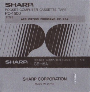
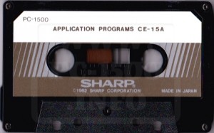
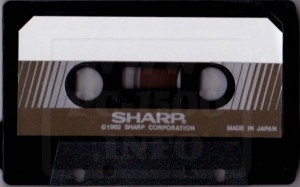
CE-15A : Application programs for the Sharp PC-1500

This Sharp software pack is a very rare item for the PC-1500.
CE-15A_001
The flat box, with size similar to the PC-1500 box, holds a tape and a user manual.
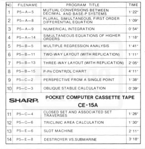
This is a library with tools and games.

CE-15A_003CE-15A_004
CE-15A_005CE-15A_006

You can download the tape content with files in WAV and BAS to load with CE-150 or CE-158.
Download tape content

Help needed :
Do you have the user manual ?
Do you know another pack from Sharp ? CE-15B ?

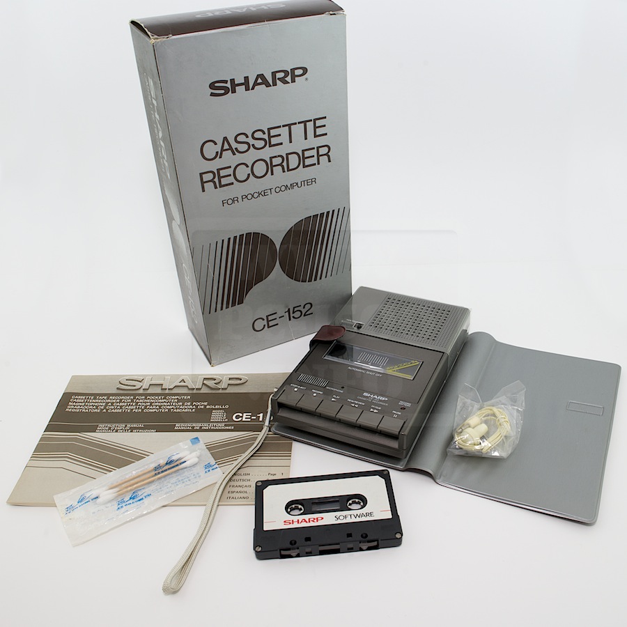
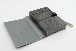
CE-152 : The Sharp tape player/recorder for the PC-1500

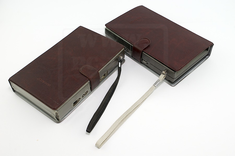
A robust pocket computer must have a robust tape player/recorder !
And the CE-152 is this tool.
It’s a well known PC-1500 + CE-150 extension, the best to save/load programs.
EMI_2614

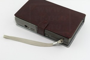
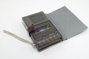
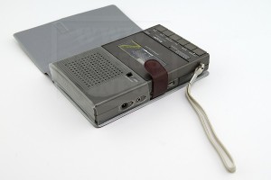
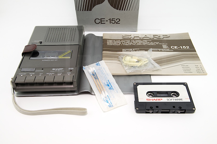
It’s a flat player in a brown protection. On the side you have the record/play connectors, a remote entry, the volume and tone potentiometers.
EMI_2427 EMI_2428
EMI_2429 EMI_2430

And in the box, the user manual, an earphone and 3… don’t know the word in english but in french it’s “coton tige”. The tape is not included but nice to see on this picture.
EMI_2619

CE-152_User_manual_MultiCE-152_User_manual_Japan
DownloadDownload

BMC : The MC-12 (Part III)

To read more a out the MC-12(A) there was an article in the german magazine CHIP :BMC_MC-12-PC-1500_ZeitungDownload article
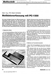
Here if the translation (may have errors)

Data acquisition with PC-1500

The More frequent use of microcomputers in the workplace of an engineer and the ever increasing amount of data that is necessary to solve a problem, led to the development of measurement and control system MC-12th The battery-operated device, when paired with the computer PC-1500 • and the Printer / Plotter CE-150, a major step towards a more rational and effective work in both the measurement and recording of various technical and physical sizes, as well as on the field of control engineering. The consistent application of modern CMOS: Technology makes the whole system for many hours mains-dependent and allows the use of mobile on site.

1 General data
The basic version of the System MC-12 has five input channels for analog signals, which can be switched by a computer-controlled multiplexer selectively on a measuring amplifier. The subsequent A / D converter with a resolution of 8 bits (corresponding to approximately 0.4%) samples the signal with a minimum cycle time of 30μs. Each input channel can sieve with a private Eingangsmeßverstärker bestükken, whereby the parallel detection of multiple physical sizes next to each other is possible (eg. 8. temperature. Pressure, tension, pH, etc.).
The maximum resolution of the instrumentation amplifier is 20 microvolts, the maximum input voltage 5V. By appropriate input amplifier is voltage up to 600V can be recorded.

The gain of the sense amplifier is set by the computer. This can be done by the user via the keyboard. but also automatically by the test program, with always the cheapest range is selected.
There is a choice between different modes. In direct mode, the measured values ​​on the LCD display (26 characters) or as a measuring beam (0.5% resolution) will be issued. Upon request, the logging is performed by the printer.

2 Operating as a transient
Its full potential can only develop the system when it is operated as a transient.
The sampling time can be set from 30 microseconds up to any number of hours, days, or weeks. This sieve is the system for the collection and processing of short-term operations (single, fleeting signals) such. As shock processes, spikes or acoustic events and Langzeitmeßaufgaben such. As temperature gradients, strains and meteorological processes.

Only the outstanding events are stored on request for long-term operations and uninteresting, stationary regions not covered (eg. As shocks. Traffic noise, etc.).
The measured data are in an 8K deep memory, which is part of the MC · 12 detained. In this case, the total memory can be reserved for a task. However, the memory can also be found in up to 30 memory blocks divided by 256 bytes each, so that max. Allow 30 different waveforms next to each store.

To select particularly interested in the parts of the signal, the ratio of pre / post-history in eight levels can be selected. The Aussteuerunganzeige the measured values ​​by means of LCD bar.
The stored values ​​can be either applied directly to two analog outputs or arithmetical previously subjected to signal processing and analysis.
A measuring process was taken and stored by MC-12, the signal can be tapped at one of the analog outputs. The output voltage is ± 5 V to 100 ohms. A single signal or an arbitrarily long lasting measuring controls so that the Y • Input a recorder. The output speed is selectable and is suitably adapted to the setting speed of the recorder. The time axis is directly from the recorder or the computer – second analog output of the MC-12 to X input of the recorder – controlled.

Two different signals y1, y2 (eg pressure with temperature) was added, may either both signals as a function of time (y1 (t), y2 (t)) are plotted, or a signal is shown as a function of the other (y1 = y1 (y2)); Here are the outputs of the MC-12 are located on the xy-inputs of the external plotter.

(Adjustable repetition time) by a constant repetition of the signal sequence is a signal to the oscilloscope can be mapped to each of the analog outputs. An additional trigger output ensures a stable display. By this way any normal oscilloscope is digital oscilloscope for Spiecher, coupled with the other advantages of the MC-12th

The integrated printer / plotter documents the results of measurements and plots with a resolution of 0.2 mm with the available four ink colors are especially useful for playing various signals in conjunction with ten line types. The scaling of the appropriate coordinate systems is done automatically by the computer.

3 Application Examples
To give an idea of ​​the possibilities offered by the system described here, are below a grater typical applications together provided for which computing functions of the PC-1500 come to fruition. The collection can of course do not claim to be complete.

3.1 detection of oscillation process
The ringing of an electric
Resonant circuit is detected by the MC-12 (Figure “J).

The yt · Scaling was performed by the computer. The calculated values ​​from the computer and k f follow directly the time function of the damped oscillation
y (t) = A * exp (-ky) * sin (2PIft)
and the differential equation when a component size is known.
L · R · y + y + y / c = 0

3.2 Frequency Analysis
A periodic progress will be measured, stored and plotted by the MC-12. Subsequently, the frequency components of the process are calculated and printed and displayed as a bar graph (Figure 4).

3.3 reverberation time
In a space to be examined E is generated in a stationary sound field using a loudspeaker. After switching off the sound source, the time course of the decrease in sound level is measured on a logarithmic scale, stored and plotted according to the physical definitions by determining a regression line, the reverberation time T is determined (Figure 5).

3.4 Programmed signal analysis and processing
The essential advantage of the combination MC-12 / PC-1500 compared to other systems, the signal processing. From the simple logarithm to the Fourier analysis extends the range of possibilities. The user has the choice, in addition to the predefined processing variants using BASIC programs to transform the measurements according to his needs and evaluate. For complicated special solutions are custom software.

3.5 Digital control and regulation
Additional applications which are beyond the scope of traditional instruments, the system MC-12 offers in the field of control engineering. With four CMOS switching outputs (75 Ohms, 50 mA, +/- 10V), two relays and two analog voltage outputs (+/- 5 V) provides many possible keys.
From a simple timer display over two-point control to complicated PID control system is the system load no application is closed. Simple programs for control and regulation are included in the system of the MC-12.
With the help of detailed documentation, the user can create self-measurement and control applications. For this, 11 Kbytes program memory in the PC-1500 free for the user.

4 Dialog oriented user guidance
The Measurement and Control System MC-12 was designed so that the user does not have to deal with the function of additional controls. All functions of the MC-12 can be controlled via the alphanumeric keypad in dialogue with the computer. Operator errors are reduced to a minimum. Incorrect entries complained about the program itself. Once made settings can be saved and recalled when needed. This reliable reproducibility of test results is ensured. An additional check of the measurement parameters are documented on the printer.