Working on the PC-1560 project need some tools.
We have to design a new system ROM but at this time don’t have to work with (E)EPROM programmers.
The best way is to look at our hardware stuff !
We most have CE-161, isn’t it ?
Ok, how does this memory module work ?
It need to be plugged on the 40 pins bus.
The PC-1500(A) schematics shows that we have these signals available on the connector:
– /Y0
– /Inhibit (active low to disable the system ROM)
CE-161 schematics shows a 40H138 (Demux) selected by /Y0 (active low) going to /G2A (active low). This signal is nothing but &0000H address.
The system ROM is at &E000H… /Y3 from the 40H139 in the PC-1500.
Simple, no ?
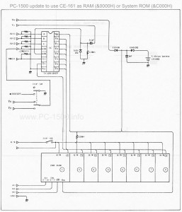
Ok, a DOUBLE hardware inverter is all we need.
The inverter will a the same time :
– connect 40H139 signal /Y0 or /Y3 to the CE-161 on /G2A
– connect /Inhibit to GND or let it to it’s high value.
The inverter must be inside the PC-1500.
Cut the strap from pin 4 of the 40H139.
Connect this pin to one side of the inverter.
Connect pin 7 to inverter’s other side.
Connecter inverter middle pin to the cutter strap.
Now you can choose CE-161 function : RAM or system ROM.
… don’t miss the /INHIBIT pin…
I will soon show your a picture of the system.
Here is the updated schematics.

CE-163 owners will have a dual ROM system… but be careful to switch ROM when powered off.
I have an original memory module CE-161
I want to change the battery
How do I open it?
Thanks